tl;dr: This blog will introduce Yao’s naive garbled circuit and state-of-the-art gate optimizations in the fancy-garbling library (implementation of BMR16). This blog also serves as a detailed writeup of DiceCTF 2025 NIL-CIRC.
The writeup of DiceCTF 2025 involves only section elementary-optimizations and section free-xor-offset-leak-attack. Readers familiar with the garbled circuit can skip to the final section. For those who are not familiar with free-XOR techniques, reading the section elementary-optimizations is enough to understand the final attack. For those who are interested in the half-gate technique of fancy-garbling library, reading section half-gate-technique is recommended. The solver can be found my ctf-writeups.
Garbled Circuit
Garbled circuit is a type of cryptographic protocol that enables secure computation between two untrusting parties. In this setup, the parties can jointly evaluate a function on their private inputs without the need for a trusted third party. In the garbled circuit protocol, the function to be evaluated is usually represented as a boolean circuit consisting of gates (such as AND, OR, and NOT). The protocol ensures that each party learns only the output of the function and nothing about the other party’s input. A necessary component in garbled circuit is the oblivious transfer (OT) protocol.
Oblivious Transfer
Alice has two secret strings $ S_0 $ and $S_1$. Bob chooses an private index $ i \in {0, 1} $. In oblivious transfer (OT), the selectable string $S_i$ is transmitted between the sender (Alice) and the receiver (Bob) in the following manner:
- Bob learns nothing about the unchosen string $ S_{1-i} $.
- Alice remains unaware of Bob’s choice $ i $.
It’s important to note that although Bob does not know the actual values of $ S_0 $ and $ S_1 $ beforehand, in practical applications, Bob typically has some encoded/side-channel information about these strings. This ensures that Bob can intelligently decide which message to retrieve rather than selecting blindly. For example, Alice usually sends the encrypted secret $c_0 = E(S_0), c_1 = E(S_1)$ in a sequential manner. This selective knowledge prevents Bob from making a random choice and allows for meaningful interaction in the protocol.
Oblivious transfer is a fundamental cryptographic primitive used in protocols such as secure multi-party computation (MPC), fair blind signature, and zero-knowledge proofs, enabling secure and private data exchange without compromising the privacy of either party.
Process of Garbled Circuit
We describe the general process of garbled circuit protocol between Alice (known as garbler) and Bob (known as evaluator) with their private input $a$ and $b$ respectively.
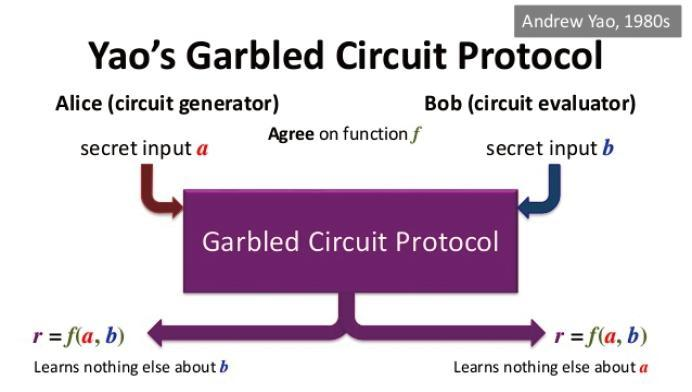
Alice and Bob agree on the public $f$ and its corresponding boolean circuit $\mathcal{F}$. Let the private input $a = (a_1, \ldots, a_{m})$ and $b = (b_1, \ldots, b_{n})$.
- Circuit Garbling: Alice garbles the public boolean circuit $\mathcal{F}$, i.e., encrypting the truth table and wire labels. Denote the truth tables of the garbled circuit as $\mathcal{F}_{g}$. In this case, every input wire is encoded as two strings $w_0, w_1$ representing input bit $0,1$ respectively.
- OT Phase: Alice sends wire labels corresponding to Bob’s private input $b$ through a batch of OT protocols. The other wire labels must kept secret to Bob.
- Alice sends the garbled circuit $\mathcal{F}_{g}$ (truth tables of all gates) and wire labels corresponding to Alice’s private input to Bob. Note that the wire labels looks random and leaks nothing about $a$ to Bob.
- Evaluation: Bob now has all input wire labels and garbled truth tables $\mathcal{F}_{g}$ and evaluate the circuit to obtain the final encrypted output.
- Reveal Output: Since Bob does not know which bit semantic the final output wire label corresponds to, Alice and Bob exchange information to learn the plain output of the public $f$.
The above protocol is too high-level and in the following, we elaborate on how to garble a boolean gate.
Circuit Garbling
To garble a circuit, we must garble both the wires and truth table of all gates.
- Wire: Alice assigns each wire in the circuit (a wire represents an input or output) two randomly generated strings, called labels: one representing the Boolean semantic 0, and the other representing 1. The length of each label is $k$ bits, where $k$ is the security parameter e.g. $k = 128$. Now, all the wires input/output of circuit $\mathcal{F}$ are random labels.
- Truth Table: Every gate can be represented as a truth table. Alice replaces the 0 and 1 in the truth table of each logic gate in the circuit with the corresponding labels.
For example, we garble the AND gate as follows:
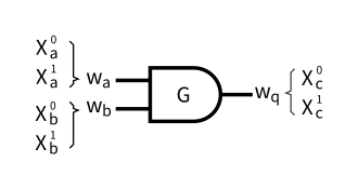
The semantic truth table and labeled truth table are as follows (actually $f$ can be any fan-in-2 gate here):
| a | b | f(a,b) | a | b | f(a,b) | |
|---|---|---|---|---|---|---|
| 0 | 0 | 0 | $X_a^0$ | $X_b^0$ | $X_c^0$ | |
| 0 | 1 | 0 | $X_a^0$ | $X_b^0$ | $X_c^0$ | |
| 1 | 0 | 0 | $X_a^1$ | $X_b^0$ | $X_c^0$ | |
| 1 | 1 | 1 | $X_a^1$ | $X_b^1$ | $X_c^1$ |
Alice needs additional encryption to prevent inferring the 0 or 1 bit semantics represented by the labels from the garbled truth table. Alice then encrypts the output entries of the truth table using the corresponding two input labels. The encrypted table is called the garbled table. This ensures that one can only decrypt the garbled table item when possessing the correct two input labels. In the table below, $Enc_{k_1, k_2}(x)$ represents a dual-key symmetric encryption algorithm (e.g., two keys are used to encrypt twice).
| Garbled Table |
|---|
| $Enc_{X_{a}^{0},X_{b}^{0}}(X_{c}^{0})$ |
| $Enc_{X_{a}^{0},X_{b}^{1}}(X_{c}^{0})$ |
| $Enc_{X_{a}^{1},X_{b}^{0}}(X_{c}^{0})$ |
| $Enc_{X_{a}^{1},X_{b}^{1}}(X_{c}^{1})$ |
After this, Alice randomly shuffles the above garbled table, making it impossible to determine the output bit from the order of the rows. To make sure Bob gets the correct wire, the construction must use an encryption scheme that makes it obvious when decrypting the “correct” ciphertext.
Now, we can see that with only the input wires and the garbled circuit $\mathcal{F}_{g}$ (truth tables of all gates), Bob can evaluate the circuit recursively and finally get the labels of output wires. After the evaluation, Bob obtains the output labels denoted as $X^{c}$ (assuming the circuit outputs only one bit), and Alice knows its mapping to the boolean value because the labels were initialized by her. Either Alice can share her information with Bob, or Bob can reveal the output to Alice, allowing one or both of them to learn the output.
A Demo of Garbled Circuit
In DiceCTF 2021, there is a challenge garbled (writeup can be found here) about the naive implementation of Yao’s garbled circuit. I use the challenge codes to illustrate the steps of garbled circuit protocol. The demo codes can be found in my ctf-writeups.
Step 0. Public Circuit and Private Inputs
Alice and Bob agree on the public boolean circuit $\mathcal{F}$ defined as follows:
# circuit_map.json
{
 "inputs" : [1, 2, 3, 4],
 "out" : [9],
 "gates" : [
     {"id" : 5, "type" : "AND", "in" : [1, 2]},
     {"id" : 6, "type" : "AND", "in" : [3, 4]},
     {"id" : 7, "type" : "AND", "in" : [5, 6]},
     {"id" : 9, "type" : "XOR", "in" : [7, 4]}
 ]
}
Alice’s input values corresponding to wires 1 and 2: $x_1, x_2$, while Bob’s input values corresponding to wires 3 and 4: $x_3, x_4$. The function represented by the circuit is:
\[f(x_1, x_2, x_3, x_4) = f(a, b) = ((x_1 \& x_2) \& (x_3 \& x_4)) \oplus x_4\]Given:
- Alice’s private input: $a = (x_1, x_2) = (1, 0)$.
- Bob’s private input: $b = (x_3, x_4) = (1, 1)$.
Step 1. Wire Generations and Garbling
Alice runs gen_key.py and gets the label pairs of all 9 wires. They are called the private keys in th code:
keys = {
1: (15233817, 1315943),
2: (15274501, 5158879),
3: (7431802, 16682547),
4: (11945610, 6753699),
5: (13849459, 4637545),
6: (10453495, 2479542),
7: (2068375, 13039971),
9: (7508273, 12723289)}
where $keys[i][b]$ is the label representing the bit $b$ of wire $i$. Alice also generates a garbled table:
G_Table = {
5: [(6829921, 11451673), (1515696, 6333149), (15107502, 8186257), (5872557, 12241756)],
6: [(13415489, 4332242), (5144037, 9578022), (15201634, 13202380), (10357348, 15158424)],
7: [(1587462, 6581034), (8356378, 2216472), (11762280, 3875959), (5982650, 7776773)],
9: [(5728291, 11896856), (12052243, 1282564), (10228672, 10487067), (6137078, 8217550)]}
where G_Table[i] is the shuffled truth table of gate with id $i$. Alice sends the garbled table G_Table and labels of her private input: $L_{a} = (x_1^1,x_2^0) = (key[1][1],key[2][0]) = (1315943 ,15274501)$ to Bob.
Remarks
In this case, the item $f(a, b) = c$ of truth table is encrypted as follows:
def encrypt(data, key1, key2):
    encrypted = encrypt_data(data, key1)
    encrypted = encrypt_data(encrypted, key2)
    return encrypted

def garble_label(key0, key1, key2):
    """
    key0, key1 = two input labels of a, b
    key2 = output label of c
    """
    gl = encrypt(key2, key0, key1)
    validation = encrypt(0, key0, key1)
    return (gl, validation)
The tuple $(g, v)$ actually encrypts an extra value $0$ for validation and Bob can find the correct output label of $c$ by checking whether the second plaintext is zero.
Step 2. Oblivious Transfer + Evaluation
In this step, Bob learns the labels of his private input:
\[L_{b} = (x_3^1,x_4^1) = (key[3][1],key[4][1]) = (16682547, 6753699)\]without revealing anything about $b = (1, 1)$ through the OT protocol. We will not explain the details of the OT protocol here, readers can refer to OT-WIKI for more details. The simplest OT protocol can be instantiated from RSA (or ECDH, see eprint/2015/267).
At this point, Bob has all the input wire labels and the garbled truth tables of the circuit, so he can begin computing the labels corresponding to the output wires. Specifically, the process involves unlocking the four entries in the garbled truth table corresponding to each logic gate. Among these entries, only one is the correct result, enabling Bob to obtain the intermediate labels of $x_5, x_6, x_7, x_9$. The label $x_9$ represents the final computation result.
Evaluate Codes
from block_cipher import decrypt
from yao_circuit import GarbledGate as Ggate
import json

# garbled truth tables
G_Table = {
    5: [(6829921, 11451673), (1515696, 6333149), (15107502, 8186257), (5872557, 12241756)],
    6: [(13415489, 4332242), (5144037, 9578022), (15201634, 13202380), (10357348, 15158424)],
    7: [(1587462, 6581034), (8356378, 2216472), (11762280, 3875959), (5982650, 7776773)],
    9: [(5728291, 11896856), (12052243, 1282564), (10228672, 10487067), (6137078, 8217550)]
    }

# Bob gets the wires
# alice_input = (keys[1][1],keys[2][0])
# bob_input = (keys[3][1],keys[4][1])
alice_input = (1315943 ,15274501)
bob_input = (16682547, 6753699)

# load circuit
circuit_filename = "circuit_map.json"
with open(circuit_filename) as json_file:
    circuit = json.load(json_file)

# evaluate the truth_table given the two input labels
def validate_the_circuit(geta_table, key0, key1):
    for g in geta_table:
        gl, v = g
        label = decrypt(gl, key0, key1)
        validation = decrypt(v, key0, key1)

        if validation == 0:
            return label

labels_dict = {}
user_input = {1: alice_input[0], 2: alice_input[1], 3: bob_input[0], 4: bob_input[1]}
gates = circuit["gates"]
wires = set()
for gate in gates:
    wires.add(gate["id"])
    wires.update(set(gate["in"]))
for wireidx in wires:
    # the index of keys[wireidx] 1 and 0 means TRUE and FALSE in garbled circuit
    if wireidx in user_input:
        labels_dict[wireidx] = user_input[wireidx]
    else:
        labels_dict[wireidx] = -1

while True:
    for gate in gates:
        out_id = gate["id"]
        input = gate["in"]

        if labels_dict[input[0]] == -1 or labels_dict[input[1]] == -1:
            continue
        else:
            garbled_table = G_Table[out_id]
            key0 = labels_dict[input[0]]
            key1 = labels_dict[input[1]]
            labels_dict[out_id] = validate_the_circuit(garbled_table, key0, key1)
    target = circuit["out"][0]
    if labels_dict[target] != -1:
        print("The target label is: ", labels_dict[target])
        break
Then Bob learns that the target label is $12723289$, but he does not know whether this label corresponds to a 0 or 1 bit of $x_9$. Alice can further reveals the bit semantic of $12723289$ to Bob (or the labels of $x_9$ can be committed at first).
Elementary Optimizations
In Yao’s garbled circuit, every fan-in-k gate needs $2^k$ ciphertexts to encrypt the truth table. Besides, the encrypted truth table must be shuffled and the evaluator is expected to try $2^{k-1}$ item decryptions to find the correct output wire label. Therefore, the early implementations of garbled circuits were extremely slow. With the emergence of numerous optimization techniques, garbled circuits have now reached practical application standards.
Point-and-Permute BMR90
A random “color bit” is appended to each wire label, so that the pair labels $(W_i^{0}, W_i^1)$ for wire $i$ have opposite color bits, i.e., $\mathcal{LSB}(W_i^0) = b, \mathcal{LSB}(W_i^1) = 1-b$. The color bit $b$ is randomly assigned and thus we can arrange the 4 ciphertexts according to color bits of the input wire labels (i.e., the first ciphertext should be the one that uses two keys having both 0 color bits, regardless of what truth value they represent). In this case, the evaluator decrypts only one ciphertext — the one indicated by the color bits of the input wire labels.
Row Reduction NPS99
When point-and-permute is applied, we can use simple one-time encryption for garbling the truth table:
\[E_{k_1, k_2}(m) = \mathcal{H}(g, k_1 \mid\mid k_2) \oplus m\]where $\mathcal{H}$ is a random oracle and $g$ is the index of gate. When garbling a gate $G(W_a, W_b)= W_c$, we can choose the two outputs $W_c^0, W_k^1$ labels such that the first ciphertext is zero. Assume that first gate ciphertext is (we treat the superscript of the wires as a color bit here):
\[E_{W_a^0, W_b^0}(W_c^0) = \mathcal{H}(g, W_a^0 \mid\mid W_b^0) \oplus W_c^0.\]We then assign $W_c^0 = \mathcal{H}(g, W_a^0 \mid\mid W_b^0) $ and only three ciphertexts of fan-in-2 gates are sent to the evaluator. We can further reduce the number of ciphertexts to 2 by polynomial interpolation in PSSW09 or a simple construction in GLNP15. Since the two techniques are not compatible with free-XOR, we will not discuss them here.
Free-XOR KS08
The free-XOR optimization has the highest practical impact on garbled circuit, which makes the XOR gate free of cost. In free XOR, the garbler generates a global secret value $\Delta \in {0,1 }^{\lambda}$ and the wire labels are chosen such that $W_i^{0} \oplus W_i^1 = \Delta$. This can be rewritten as $W_i^{x} = W_i^{0} \oplus (x\Delta)$. For an XOR gate $G(W_a, W_b)= W_c$, we have:
\[W_a^x \oplus W_b^y = (W_a^0 \oplus W_b^0) \oplus (x \oplus y) \Delta\]We assign $W_c^0 = W_a^0 \oplus W_b^0$ as the ‘false’ wire label and simply XORing two input wire labels of XOR gate that encodes $a, b$ results in the output wire label encoding $c = a \oplus b$. As a consequence, garbled XOR gate can be evaluated without any cryptographic operations by the evaluator or any garbled-gate ciphertexts. Note that by choosing $\mathcal{LSB}(\Delta) = 1$ (or other definition of the color bit), the free-XOR technique is compatible with point-and-permute and row-reduction techniques, which results in 3 ciphertexts per AND gate and 0 per XOR.
Half-Gate Technique
The half-gate technique ZRE15 is a powerful optimization that allows the use of only two ciphertexts per AND, OR, NOR, NAND gate, while being compatible with free-XOR, which results in two ciphertexts per AND/OR gate and 0 per XOR gate. Later in CRYPTO’21, Mike Rosulek and Lawrence Roy RR21 improved the half-gate technique, allowing 1.5 ciphertexts per AND gate and 0 per XOR gate. This section involves only techniques introduced in ZRE15.
Half-Gate Decomposition
The half-gate technique allows two ciphertexts per AND gate which is compatible with free-XOR. Denote $(A, A \oplus \Delta)$ and $(B, B \oplus \Delta)$ as the input wire labels to an AND gate, and $(C, C \oplus \Delta)$ as the output wire labels, where $A, B, C$ each encodes ‘false’ (bit 0) of $a, b, c$. Let $\mathcal{H}(\cdot)$ be a random oracle. The half-gate technique splits the AND gate $c = a \land b$ as follows:
- Case $a = 0$: AND gate degenerate to a unary gate that always outputs false.
- Case $a = 1$: AND gate degenerate to a unary identity gate that always outputs its input.
Now, note that the AND gate can be split into two half gate:
\[\begin{aligned} c &= a \land b \\ &= a \land (r \oplus r \oplus b) \\ & = (a \land r) \oplus (a \land (r \oplus b)) \end{aligned}\]Suppose the generator chooses a uniformly random bit $r$ and the bit $r$ is known to the generator. In practical case, the generator will choose $r$ to be the color bit of the false wire label on wire $b$ which reveals the value of $r \oplus b$ to the evaluator because for wire $W_i^b$, its color bit is exactly $r \oplus b$. In the following, we consider two half AND gates where exactly one input is known to either the garbler or evaluator.
Generator Half-Gate. In the generator’s view, the bit $r$ is known. The generator generates the following two ciphertexts to evaluate $a \land r$:
\[\begin{cases} \mathcal{H}(A) \oplus C \\ \mathcal{H}(A \oplus \Delta) \oplus C \oplus r\Delta \end{cases}\]These are then suitably permuted according to the color bits of $A$. The evaluator decrypts this by hashing the wire label for $A$. If $r = 0$, the evaluator always gets $C$ (zero bit of output). If $r = 1$, the evaluator gets either $C$ or $C \oplus \Delta$ corresponding the bit of $a$. We can further apply the row-reduction technique. We choose $C$ (as $\mathcal{H}(B), \mathcal{H}(B \oplus R)$ or $\mathcal{H}(B \oplus R) \oplus R$ depending on the color bits and the value of $r$) such that the first of the two ciphertexts is the all-zero ciphertext.
Evaluator Half-Gate. In the evaluator’s view, the value of color bit denoted as $s := r \oplus b$ is known. When $s = 0$, the evaluator should always obtain output wire label $C$ (zero bit). When $s = 1$, it’s enough for the evaluator to obtain $C \oplus A$. In can then XOR $C \oplus A$ with its label of $a$ (either $A$ or $A \oplus \Delta$) to get the correct output as $C$ or $C \oplus \Delta$. In the generator’s view, it knows the value of $r$, therefore, we denote the symbol $S$ as the label wire of $s$:
\[S = \begin{cases} B, & r = 0 \\ B \oplus \Delta, &r = 1 \end{cases}\]The generator generates the following two ciphertexts for the evaluator to evaluate $a \land (r \oplus b) = a \land s$:
\[\begin{cases} G_1 = \mathcal{H}(S) \oplus C \\ G_2 = \mathcal{H}(S \oplus \Delta) \oplus C \oplus A \end{cases}\]The ciphertexts do not have to be permuted here. They can be arranged according to the truth value of $s$ as shown here, since the evaluator already knows $s$. In the evaluator’s side, it computes the output label based on the value of $s$ and label $S \oplus s \Delta$:
\[\begin{cases} s = 0: &G_1 \oplus \mathcal{H}(S \oplus s \Delta) = C \\ s = 1: &G_2 \oplus \mathcal{H}(S \oplus s \Delta) \oplus A \oplus a \Delta = C \oplus a \Delta \\ \end{cases}\]This shows that we can correctly evaluate the half gate. Again, we can remove the first ciphertext using garbled row-reduction. We choose $C = \mathcal{H}(S)$ so that the first ciphertext becomes all-zeroes and is not sent to the evaluator.
Now, two halves make a whole ADD gate. We denote $C_{G}, C_{E}$ as the outputs of generator’s and evaluator’s half gates, respectively. Intuitively, we can XOR the two ciphertexts of half gates to obtain the ciphertexts of the original AND gate.
Two Halves = One Whole
Let the AND gate’s input labels be $W_a^{0}, W_a^{1}, W_b^{0}, W_b^{1}$ and output labels $W_{c}^0, W_{c}^1$. Let $W_{G_c}, W_{G_e}$ be the output labels of generator’s and evaluator’s half-gates. The global offset value for free-XOR is $\Delta$, i.e., $W_{i}^{0} \oplus W_{i}^{1} = \Delta$ for all $i$. Denote the color bits of $W_a^{0}, W_b^{0}$ as $p_a$ and $p_b$ respectively.
Step 1 Generator Half-Gate. Before row-reduction and permutation, the generator generates the following ciphertexts:
\[\begin{cases} \mathcal{H}(W_a^0) \oplus W_{G_c}^0 \\ \mathcal{H}(W_a^1) \oplus W_{G_c}^0 \oplus p_b \Delta \end{cases}\]After row-reduction and permutation according to color bits $p_a, 1 \oplus p_a$, (we assume $p_a$ = 0 here for simplicity), the generator assigns
\[W_{G_c}^0 := \mathcal{H}(W_a^0)\]and saves
\[T_{G_c} = \mathcal{H}(W_a^1) \oplus \mathcal{H}(W_a^0) \oplus p_b \Delta\]as the garbled truth table item (which will later be sent to the evaluator).
Step 2 Evaluator Half-Gate. Before row-reduction, the generator generates the following ciphertexts:
\[\begin{cases} \mathcal{H}(W_b^{p_b}) \oplus W_{E_c}^0 \\ \mathcal{H}(W_b^{p_b \oplus 1}) \oplus W_{E_c}^0 \oplus W_{a}^0 \end{cases}\]After row-reduction and (no permutation here), the generator assigns
\[W_{E_c}^0 := \mathcal{H}(W_b^{p_b})\]and saves
\[T_{E_c} = \mathcal{H}(W_b^{1}) \oplus \mathcal{H}(W_{b}^0) \oplus W_{a}^0\]as the garbled truth table item (which will later be sent to the evaluator).
Step 3 Combine Two Halves. The generator sends the garbled truth table items $T_{G_c}, T_{E_c}$ to the evaluator. The generator XORs the two output labels of half-gates to obtain the output label of the original AND gate:
\[W_{c}^{0} := W_{E_c}^0 \oplus W_{G_c}^0 = \mathcal{H}(W_a^0) \oplus \mathcal{H}(W_b^{p_b})\]Finally, the generator sends $T_{G_c}, T_{G_e}$ to the evaluator. Denote the boolean value of wire $a, b$ as $x_{a}, x_{b}$ and let $p_a$ be $0$ for simplicity (ignore the first permutation). The evaluator evaluates the two half gates to get $W_{G_c}, W_{E_c}$ based on the color bits of $W_a^{x_a}, W_b^{x_b}$ as follows:
\[\begin{cases} W_{G_c} &= \mathcal{H}(W_{a}^{x_a}) \oplus x_a T_{G_c} \\ &= x_a\mathcal{H}(W_{a}^{1}) \oplus (x_a \oplus 1)\mathcal{H}(W_{a}^{0}) \oplus x_a(\mathcal{H}(W_a^1) \oplus \mathcal{H}(W_a^0) \oplus p_b \Delta)\\ &= \mathcal{H}(W_a^0) \oplus (x_a p_b) \Delta\\ &= W_{G_c}^{x_a p_b} \\ W_{E_{c}} &= \mathcal{H}(W_{b}^{x_{b}}) \oplus (p_b \oplus x_b) (T_{E_c} \oplus W_{a}^{x_{a}}) \\ &= x_b\mathcal{H}(W_{b}^{1}) \oplus (x_b \oplus 1)\mathcal{H}(W_{b}^{0}) \oplus (p_b \oplus x_b)(\mathcal{H}(W_b^{1}) \oplus \mathcal{H}(W_{b}^0) \oplus W_{a}^0 \oplus W_{a}^{x_{a}}) \\ &= p_b \mathcal{H}(W_{b}^{1}) \oplus ( p_b \oplus 1)\mathcal{H}(W_{b}^{0}) \oplus (p_b \oplus x_b)x_a \Delta \\ &= \mathcal{H}(W_{b}^{p_b}) \oplus (p_b \oplus x_b)x_a \Delta \\ &= W_{E_c}^{ x_a(p_b \oplus x_b)} \end{cases}\]Use the free-XOR to get the final output label as
\[W_c = W_{G_c} \oplus W_{E_c} = W_{c}^{x_a p_b \oplus x_a p_b \oplus x_a x_b} = W_c^{x_a x_b}.\]This shows our scheme evaluates the ADD gate correctly with only two ciphertexts using free-XOR. This half-gates can generalize to any gate whose truth table contains an odd number of ones (e.g. AND, NAND, OR, NOR, etc.). All such gates can be expressed as the form of
\[f(v_a, v_b) = (\alpha_a \oplus v_a) \land (\alpha_b \oplus v_b) \oplus \alpha_c\]for constants $\alpha_a, \alpha_b, \alpha_c$. The generic half gates can be described as follows:
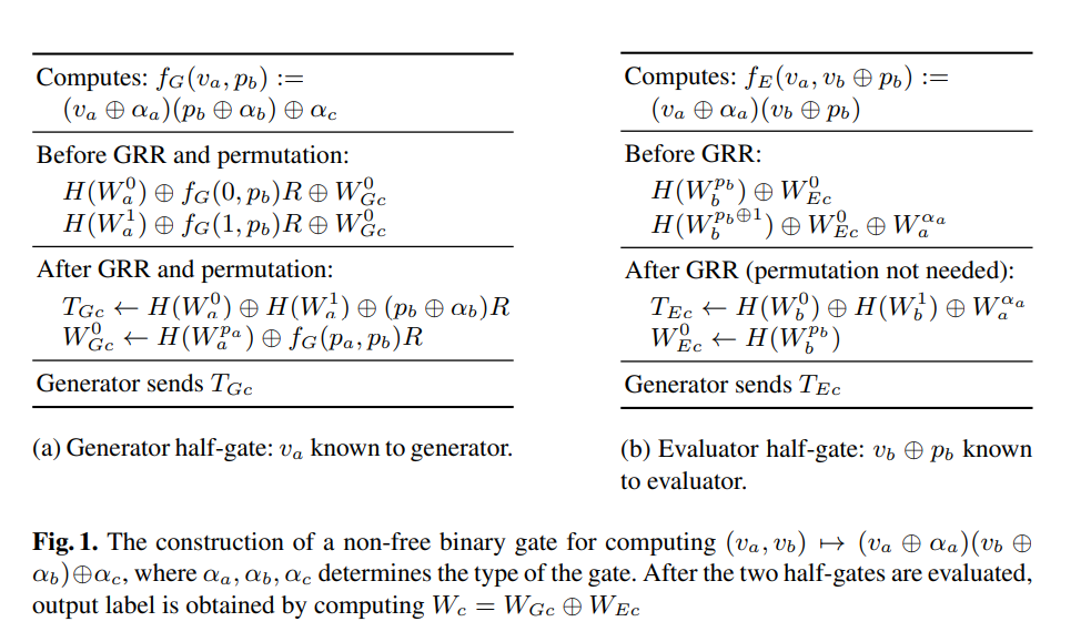
Typo: In generator’s half-gate, the value $p_b$ is known to generator.
Arithmetic Garbled Circuits BMR16
The BMR16 scheme generalizes the free-XOR and half-gates to arithmetic circuits (vectors modular $n$), resulting in garbled circuits with free addition, weighted threshold gates with cost independent of fan-in, and exponentiation by a fixed exponent with cost independent of the exponent. Specifically, BMR16 gives an exponential improvement over the state of the art for threshold gates (including AND/OR gates) of high fan-in. The fancy-garbling library implements a really fast version of BMR16 with additional optimizations. We omit details of BMR16 here since most of the techniques have been introduced above.
Free-XOR Offset Leak
When free-XOR is implemented in a garbled circuit, one should be careful that a malicious OT receiver may destroy the security and privacy of the garbled circuit. In the standard OT protocol, although it’s impossible (when implemented and used correctly) for the receiver to obtain two messages $x_0, x_1$ simultaneously, a dishonest receiver may carefully construct the input so that the value of some function $f(x_0, x_1)$ is leaked (e.g., we can easily recover the value of $f(x_0, x_1) = x_0 \pm x_1 \mod N$ in the RSA OT protocol). In free-XOR, the two messages to be transmitted in the OT protocol are $W_i^0, W_i^{1}$ where $\Delta = W_i^0 \oplus W_i^{1}$ holds for all $i$. Therefore, if we can recover $f(W_i^0, W_i^{1}) = W_i^0 \oplus W_i^{1} = \Delta$, we can actually recover all labels in the circuit.
In challenge NIL-CIRC, the Chou-Orlandi OT protocol is implemented in fancy-garbling library. We can recover the server’s private key as follows:
- Run the Chou-Orlandi OT protocol with a malicious receiver. This can leak the global offset $\Delta$ of free-XOR which allows us to recover all the wire label pairs in the garbled circuit.
- Use the unbalanced AND gate to recover the bit semantics of wire label pairs.
- Construct linear equations to recover the private key bits based on the bit semantics of wire labels.
Chou-Orlandi OT protocol
The Chou-Orlandi OT protocol eprint/2015/267 is claimed to be UC-secure in the random oracle model under dynamic corruptions.
OT Based on ECDH
The sender has two secrets $m_0, m_1$. Let $G$ be the public generator on curve-25519 and $q$ be the order of $G$. All the arithmetic operations are performed over curve-25519. Denote $\mathcal{H}$ as a random oracle. The Chou-Orlandi OT protocol runs as follows:
-
The sender samples $y \in_{R} \mathbb{Z}_{q}$ and sends $Y= y \cdot G$ to the receiver.
-
The receiver samples $r \in_{R} \mathbb{Z}_{q}$ and chooses a challenge based on his secret bit $b$.
\[R = \begin{cases} r \cdot G, & b= 0 \\ Y - r \cdot G, & b= 1 \end{cases}\]Save $k_b = \mathcal{H}(i, r \cdot Y)$ where $i$ is a counter for performing batch OT protocols and send $R$ to the sender.
-
The server computes two one-time keys:
\[\begin{cases} k_0 = \mathcal{H}(i, y R) \\ k_1 = \mathcal{H}(i, yY - yR) \\ \end{cases}\]and encrypts the two messages:
\[\begin{cases} c_0 = m_0 \oplus k_0 \\ c_1 = m_1 \oplus k_1 \\ \end{cases}\]Send pair $(c_0, c_1)$ to the receiver.
-
Note that:
\[\begin{cases} b=0: & k_0 = \mathcal{H}(i, yr \cdot G) = k_b \\ b=1: & k_1 = \mathcal{H}(i, yY - yY + yR) = k_b \\ \end{cases}\]The receiver retrieves his message $m_b$ as follows:
\[m_b = c_b \oplus k_b\]
This is a perfect phase to run a malicious OT receiver attack to recover the global offset $\Delta$ of free-XOR. The idea is to make:
\[k_0 = k_1 \implies yR = y Y - yR \implies R = \frac{1}{2}Y.\]When receiving any input wire label $W_i^{b}$, the malicious receiver can recover:
\[\Delta = c_0 \oplus c_1 = m_0 \oplus m_1 = W_{i}^0 \oplus W_{i}^{1}.\]For all other OT protocols, the malicious receiver runs honestly. With $\Delta$ and free-XOR, the attacker can recover both labels for each wire.
Recovering Private Inputs
No matter what optimizations are applied, the real truth table remains the same to keep the functionality. Therefore, we can distinguish the bit semantics represented by the wire labels from an unbalanced truth table. For a balanced gate such as XOR, we cannot decide the bit semantics of wire labels from a shuffled truth table. Take the AND gate as an example. Let the input wires be $W_{a}^{x}, W_{a}^{y}$ and $W_{b}^{u}, W_{b}^{v}$. Given the garbled circuit, we can evaluate the AND gate four times using input pairs:
\[(W_a^x, W_b^u),(W_a^x, W_b^v), (W_a^y, W_b^u),(W_a^y, W_b^v)\]and will only obtain two output labels $W_c^{0}, W_c^{1}$. We can determine that the output label occurring thrice is the label $W_c^0$ representing ‘false’ semantics and the other occurring once is the label $W_c^1$ representing ‘true’ semantics. Supposing the two labels $W_a^x, W_b^{v}$ outputs the $W_c^{1}$, we then know $W_a^1 = W_a^x$ and $W_b^1 = W_b^v$, respectively.
If we have the garbled circuit and all the input label pairs $(W_i^0, W_{i}^1)$ with their bit semantics unknown, we then evaluate the whole gates using arbitrary input $(x_1, \ldots, x_n)$. When it comes to an AND gate, we have two input labels $W_0, W_1$. Using free-XOR, we reconstruct the four input wire labels as $(W_{0}, W_{0} \oplus \Delta)$ and $(W_{1}, W_{1} \oplus \Delta)$ and evaluate the table four times to determine the bit semantics of $W_0, W_1$. Meanwhile, since the circuit is public, we know the algebraic expression (polynomial) of wires related to $W_0$ and $W_1$ and build an equation of original inputs $(x_1, \cdots, x_n)$. Collect enough equations and solves for $(x_1, \ldots, x_n)$ corresponding to our evaluated labels. Recall that we use one OT (e.g. input $0$) to recover the offset $\Delta$, all the wires related to input 0 will be ignored during evaluation. We can redefine a leaky_and evaluation in fancy-garbling:
impl<C: AbstractChannel> CustomAND for Evaluator<C, WireMod2> {
    // returns (output_label, A_bit, B_bit, success) where A_bit, B_bit are the bit semantics of A, B.
    // `success` indicates whether the leak sucesses.
    fn leaky_and(&mut self, A: &Self::Item, B: &Self::Item, delta: &Self::Item) -> Result<(Self::Item, bool, bool, bool), Self::Error> {
        let gate0 = self.channel.read_block()?;
        let gate1 = self.channel.read_block()?;
        let A_inv = A.plus(delta);
        let B_inv = B.plus(delta);
        let inputs = [
            (A, B),
            (A, &B_inv),
            (&A_inv, B),
            (&A_inv, &B_inv),
        ];

        let outs = inputs.iter().map(|(a, b)| {
            let res = self.evaluate_and_gate(a, b, &gate0, &gate1);
            self.current_gate -= 1;
            res
        }).collect::<Vec<_>>();
        self.current_gate += 1;

        if outs[0] == outs[1] && outs[0] == outs[2] {
            return Ok((outs[0], false, false, true));
        } else if outs[0] == outs[1] && outs[0] == outs[3] {
            return Ok((outs[0], false, true, true));
        } else if outs[0] == outs[2] && outs[0] == outs[3] {
            return Ok((outs[0], true, false, true));
        } else if outs[1] == outs[2] && outs[1] == outs[3] {
            return Ok((outs[0], true, true, true));
        }
        // If we get here, we have a wrong label or a wrong gate, or a wrong delta
        return Ok((outs[0], false, false, false));
    }
}
Then we export all known bits of the wires into a file and solve linear equations to recover key bits in SageMath. In my local test, we can recover 124 key bits and brute force 4 bits to decrypt the flag. Exploiting codes can be found in my ctf-writeups.